JHS Pedals are one of my favorite guitar effects companies. They make some of the most sought-after pedals and offer some of the most unique and innovative pedal modifications. I don’t have any experience with their original products, but I have had a few of my own pedals modified by them – Boss TR-2, DD-5 and MXR Dyna Comp.
Now, with that said, I do have one complaint…and it’s about the quality of their workmanship.
It. Is. Sloppy…
Again, I’ve only had experience with their modifications so I can’t speak to the quality of their original products. I trust that they’re good, but I really wouldn’t know.
My modified Boss pedals both incorporate an additional top-mounted switch for added functionality. To accommodate this switch, the modification requires that a hole be cut out underneath the switch plate (where the 9V battery would typically be). This hole was one of the first signs of this sloppy workmanship that I’m talking about. I really don’t know their means of creating this hole, but from the looks of it, it seems as if it was done by hammer and chisel. Or if they did have the appropriate tools, the individual working on my pedal just possessed horrible motor skills. Basically, the the edges were pretty jagged. But I mean, who cares, right? It’s only cosmetic, and for the most part, unseen.
Well, ok. But the problem I noticed was that they didn’t cut enough of the hole to accommodate the switch.
To back up a bit…when you stomp on a Boss pedal, the top plate and the main chassis of the pedal should meet, and there should be a bit of a “clank” sound. In some cases, the rubber grommet that lines the hole where the end-screw goes will dampen that sound. But for the most part the plate should go down all the way.  What I noticed was that near the end of the depression, the main switch felt kinda “squishy.” So I opened it up.

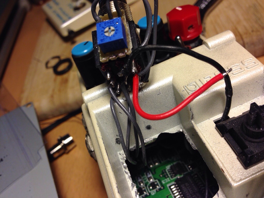
The photo above is what’s immediately under the main switch plate. The thing with all the wires sticking out of it is the top-mounted additional switch that I’ve detached from the switch plate (in the background). Going down near the cut-out, do you see the two rub marks right above the hole? Those marks were made as a result of the bottom portion of the additional switch making contact with the chassis. This was the “squishy” feeling. This is bad. It’s unnecessary binding of components; It’s wear-and-tear where there shouldn’t be any. Also, that black wire coming out of its own hole right next to the plastic switch? What is that? Why wasn’t it routed with the rest of the other wires? No idea.
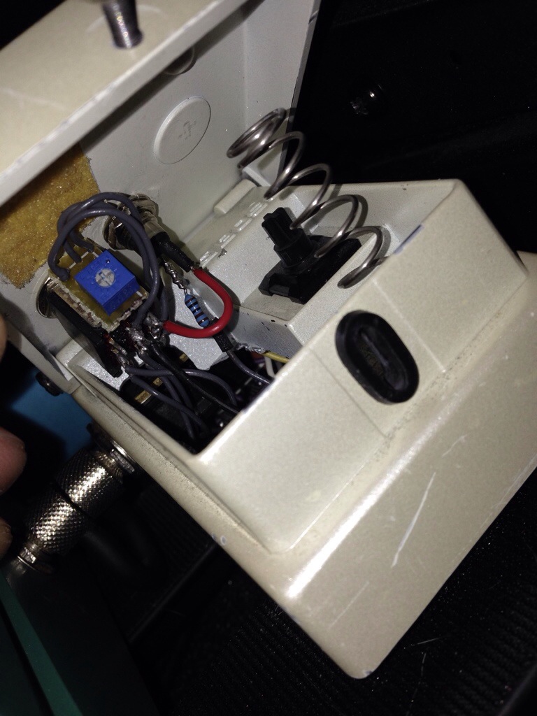
This picture above was taken after I had addressed a handful of issues including the issue about the unnecessary binding of the additional switch. You can see where I carved out an additional cut-out (dremel w/ cutting bit) so that the additional switch has room to back up when the main switch plate is pressed down. I also redid the connections of the LED (and while I was at it, I thought I’d change it from red to pink and added a metal LED holder, just for looks). Previously the positive (I think) lead was directly soldered on the the bottom of the switch. But I didn’t like this so I snipped it and made the connection with that red wire you see there. The other lead for the LED is currently connected in the same fashion as before, although I think it’s much more secure now. I also rerouted that lone black wire through the main cut-out so it could be with the rest of its wire buddies.
Not surprisingly, I noticed I had to do the same amount of clean-up for my modded TR-2 as well. I faced the same issue with the switch not having enough room to move. This  time, the cut-out job was even more shoddy than the one in the DD-5! Also, I noticed that the battery connector was left inside the compartment. Why? There is no longer any room for the battery. Probably just an oversight. Who knows. And I noticed that during the clean-up, a wire connection was severed. Oops! My bad. Upon closer inspection, the wire that was severed just wasn’t properly stripped; basically, only a few strands of the wire remained and these remaining strands were subsequently soldered onto the leads of the additional switch. In addition to this bad soldering job, I felt that the switch could have had more slack in general; the top plate barely opens up when I unscrew the end-screw of the top plate. It should be able to do this. I also noticed a little stub of a wire (with insulation in tact). I know it achieves the same result, but why wasn’t this wire just de-soldered instead of left dangling?
Alright. Well, I had no idea that this post was going to contain this many words. But I guess I was just sorta surprised at the sloppiness I encountered when I had to open up my pedals. The components pushing up against each other is sort of a big deal to me. The sloppy wiring/soldering job is of some concern, but not as big of a deal. Am I ever going to get a pedal modified by JHS? Sure. But now I’ll kinda know what to expect.  The silver lining in all of this is that I get a certain degree of satisfaction knowing that I have made these improvements. But, you know, I shouldn’t have had to. Oh well.
The End.


Hey! I am wanting to do a mod them! wanted to see inside (board) would have a picture to show me? Thank you
sorry, man. too much work.
I can imagine! I’m doing this on my DD5 but I understood it was not the four wires in DPTD being three in trimpod
But Thanks!
Hi dear friend, Could you please tell me the values of the trimpot?
Thanks
the trimpot will be the same value as the the original pot, since its effectively another one of them set to a different position. instead of using an internal trimpot, remove the original pot and replace with a dual concentric pot and wire it the same as if you were using a trimmer. this way you can have full control over both pots on the fly, without having to open up the pedal in order to change it.